Pump Guide

  • Quick Links
> Types of pumps and Applications - Click here
> Pump Curve - Click here
> Intro to pump - Click Here
> Alignment of the pump - Click here
> Understanding pump recirculation – Click here
> Slip Factor – Click Here
> Velocity Triangle – Click Here
> Restoring Pumps with Coatings – Click here
> Centrifugal pump vs. rotary pump - Click here
> Centrifugal pump efficiency - Click here
> Balancing Pump Impellers - Click Here
> Gusset - Click here
> Effect of increasing the number of Impeller vanes on the pump performance - Click Here
What causes Galling of pump material - Click Here
> Basic Materials used for the pump parts - Click Here
> API material classification - Click Here
> What is a Mechanical seal? - Click Here
> Arrangement 1, 2, and 3 type seal – 00 - Click Here
> Arrangement 1, 2, and 3 type seal – 01 - Click Here
> Mechanical Seal - Balanced & Unbalanced type - Click Here
> Mechanical Seal - Pusher & Non-Pusher type - Click here
> Seal Orientations - Click Here                        
Static Head and Dynamic Head - Click Here
> RTJ Flanges - Click Here
> Pump Couplings - Click Here
> Cryogenic Pump - Click Here
> Pump Power - Click HereExample of Power calculation
> Installed power - Click Here
> Friction Loss - Click Here
> Affinity Law - Click Here
> Bernoulli’s Principle - Click Here
> Hydrodynamic Lubrication - Click Here
> Centrifugal pump performance curve - Click Here
> Pump NPSH - Click Here + Click Here
> Pump starting NPSH - Click Here 
> Barometer - Click Here
> Impeller Partial Center Shroud vs. Full Center Shroud - Click here
How to Increase Pump NPSH - Click Here
Pump Casing Hydrostatic Test - Click Here
> Difference between Rolling element Bearing and Hydrodynamic fluid film Bearing - Click Here
Centrifugal Pump Performance Test - Click Here
> Pulsation Dampeners and Metering pump - Click Here
Diaphragm pump concept design - Click here
> How does O-Ring work - Click Here
Pump De-Rating - Click Here
> Max. Viscosity pump can handle - Click Here
> NOL BHP - Click Here
> API Seal Plans - Click Here
  • Frequently used words

> MTBR - Mean Time Between Repairs
> LDAR - Leak Detection and Repair
> HRVOC - Highly Reactive Volatile Organic Compounds
> LOI - Letter of Indent
> CIN - Customer Identification Number
> GRN - Goods Receive Note
> LR - Laurie Receipt
> TPI - Third-Party Inspection
> PDI - Pre-Dispatch Inspection
> LC - letter of Credit
> CDS - Certified Data Sheet
> VAF – Verification Audit Form
> NACE - National Association of Corrosion Engineers
A.I.S.I. - American Iron and Steel Institute
> CMU - Curve Maintenance Utility
> PSS - Pump Selection System
  • Key Points
> Pressure = Force / Area
> Pumps are in series - High Head
> Pumps are in Parallel - High Flow
> API region preferred for pump operating - 70 to 120%
> Flinger used - above 45 degrees temperature - we avoid using Inpro there
> Below BEP - Recirculation losses are higher
> Cut water - Avoid Recirculation
> Max. Allowable bending for Shaft - 0.005"
> Acceptable Runout for shaft - 0.001"
> Full assembled rotor allowable - runout 0.001"
> Impeller Wear ring installation - Heating
> Case Wear ring installation – Cooling
> RPM = 120 x (Frequency / Motor Pole)
> Head = 2.31 x Pressure / Specific Gravity
> Specific Gravity = Density of the part / Density of reference part
> Water @ 72° F (22° C) = Specific Gravity = 1
> Gauge Pressure - Pressure above/below atmosphere pressure
> Absolute Pressure - Pressure above absolute vacuum
> Bare pump - Pump without Auxiliary Piping and motor
> Impeller having small discharge - High Head and Low Flow
> Volute width (b3) is made 1.6 to 2.0 times the impeller width (b2)
> Tap thread length - 1.5 x Thread Diameter
> Holes - 1A/2A/3A - External Threads, 1B/2B/3B - Internal Thread
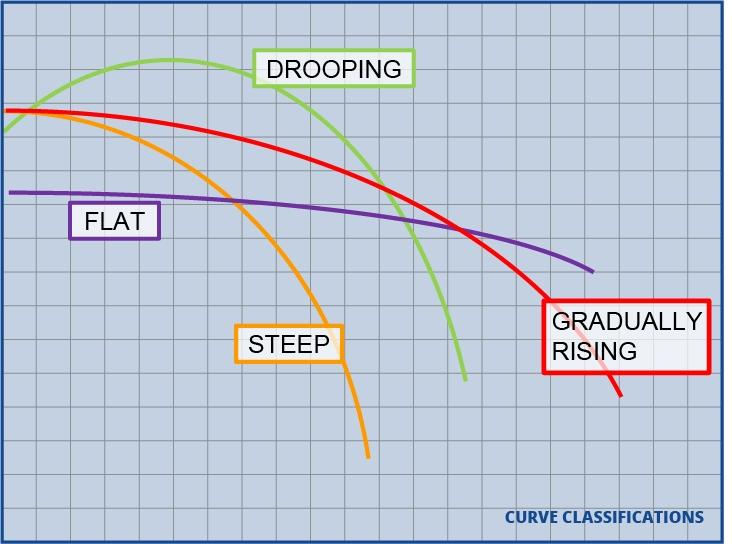
> As specific speed increases, the H-Q curve becomes more stable.
> Pumps with unstable curves will develop more Head and be more efficient than their continuously rising counterparts.
> The Hydraulic Institute has permitted a drop in head of 3 % to be accepted as evidence that cavitation is present under test conditions
> The term "high speed" does not refer to RPM, but to blade peripheral velocities above 160 ft. /sec. Thus a pump operating at high RPM with a small eye diameter may be less critical than a slower pump with a larger eye.
> Single-volute designs are used mainly on low capacity, low specific speed pumps or pumps for special applications such as variable slurries or solids handling
> Double-volute pump casings should not be used in low-flow (below 400 GPM) single-stage pumps.
> Rotameter used for collecting data on the flow rate
> A good rule-of-thumb is to require that NPSHa be greater than NPSHr by at least 10% and not less than 5 Ft.
OH-6 Pump can be oriented vertically as well as horizontally
  • Ambient temperature

Ambient temperature is the air temperature of an environment or object. 
In computing, ambient temperature refers to the air temperature surrounding computing equipment. 
This measurement is crucial for equipment function and longevity

  • Drooping

A drooping pump curve is a characteristic head-flow pump
performance curve that does not continuously rise when moving from the best efficiency point (BEP) back to shutoff. In fact, the curve reaches a high point prior to zero flow, then declines as it approaches shutoff.

  • What is Shutoff

The shutoff head is the head a pump will develop when operating against a closed discharge valve. The terms dead-heading and zero flow are sometimes used interchangeably with the term shutoff.

In some pumping systems, in order to purge all air out of the piping system or to minimize pressure fluctuations within the piping, it is necessary to start and stop a centrifugal pump against a closed discharge valve. During this scenario, the pump will be required to operate at shutoff for a period of time that is usually no more than 30 seconds long. 

The duration of this cycle should be determined in coordination with the pump manufacturer, and continuous operation at shutoff should be carefully avoided.

During the design phase of a project, a pump manufacturer should be made aware of the requirement to operate at shutoff will apply to the project. This is so that the manufacturer can ensure that the pump casing can withstand the pressure developed at shutoff and that the motor and mechanical components have been sized with consideration given to power demands at shutoff.
  • Suction-lift configuration

A suction-lift configuration is one where the liquid being pumped is located below the pump. For example, imagine a large underground basin full of liquid, and a pump set on top of the basin drawing water up out of the basin through a pipe that extends down into the basin.

  • Centrifugal Pumps Must be Primed

Centrifugal pumps can’t pump air,

Since they operate by imparting velocity to a liquid, they must be filled with liquid in order to operate. 

However, there is a special type of centrifugal pump that can evacuate the air from its suction line. This type of pump is called a self-priming pump.

  • How do Self-Priming Pumps Work?

It’s important to keep in mind that even self-priming pumps must have an adequate amount of water inside the pump casing before being energized. 

Running a self-priming pump while empty will result in a mechanical seal failure and may cause damage to other internal components. 
Self-priming pumps are designed to retain the amount of water needed for self-priming. So once a self-priming pump has run once, it will automatically contain enough water to self-prime. 
However, when starting an empty self-primer, the pump must be primed manually.
  • Unit of Kinetic viscosity – SSU
Say bolt Universal Seconds, SSU, is the kinematic viscosity as determined by the time in seconds required for 60 cc of fluid to flow through a standard orifice.
  • Viscosity
It is important to realize that the size of the internal flow passages has a significant effect on the losses, thus the smaller the pump is, the greater the effects of viscosity. As the physical size of a pump increases, the maximum viscosity it can handle increases.
  • Horsepower
Horsepower absorbed by the pump will vary directly with the change in specific gravity, A pump being purchased to handle a hydrocarbon of 0.5 specific gravity will normally have a motor rating with some margin over end-of-curve horsepower. During factory testing on the water with 1.0 specific gravity, the absorbed horsepower will be two times that of field operation.


  • Specific Speed

> Specific speed is always calculated at the best efficiency point (BEP) with maximum impeller diameter and single stage only.
> It is a characteristic of the discharge side
> For pumps of high specific speed (2,500-4,000), impeller trim should be limited to 90% of the original diameter
  • Suction Specific Speed


  • Circular volute design
> For small, high head, low specific speed (Ns 500-600) pumps.
> For a pump casing that must accommodate several impeller sizes
> For a pump in which foundry limitations have dictated an overly    wide impeller b2
> For a pump that must use a fabricated casing.
> For a pump that requires the volute passage to be machined in the case casting.
  • Stud
A 1/16 deep relief should be machined around each stud at the split. At each stud at assembly, the metal will rise. The relief will allow the gasket to lay flat, reduce the gasket area, and increase gasket unit pressure.

As a guide to selecting bolt size use:

Number of bolts = (P X A) / (S X Ar)

Notation -

P – Hydro test pressure (psi)
A - Total area at split minus the total area of bolt hole relief diameter (sq. in.)
S - Allowable bolt stress (psi)
Ar - Root area of bolt thread (sq. in.)
  • Functions of pump parts
> Impeller - to Increase Liquid's Velocity
> Casing - to convert Velocity into Pressure/Head
> Larger the Impeller - High Velocity - High Head
  • Inertia
is the resistance of any physical object to a change in its velocity/amount of resistance to a change in velocity/resistance to a change in motion
  • Oil Mist Lubrication
  • Minimum size of fillet weld
                   
  • Investment Casting vs. Sand Casting

  • Impeller Underfile 
  • ISO Fits
  • Wearing Tolerances
  • Types of Wear
  
  • Difference between Cavitation and Flashing
Cavitation: Cavitation happens in pumps, nozzles, etc. where the local fluid pressure is lower than the fluid's vapor pressure. The lower pressure causes vapor bubbles to form & move with the moving fluid. When these bubbles impinge on the parts of the machine, it erodes the parts severely, necessitating their replacement. This is called cavitation.

Flashing: The phenomenon of vapor formation due to a pressure lower than vapor pressure is the same in flashing. The main difference is, flashing is a desirable process done purposefully in a flash tank to use the resulting vapor elsewhere in process plants, while cavitation is an undesirable process, resulting in physical wear of machinery.
  • Repeller/Expeller
Expeller / Repeller design pumps are used in applications where there is a possibility of dry run conditions, liquid slurries up to 40%, or crystallizing liquids, all of which are damaging to mechanical seals or packing.

Expeller/Repeller/hydrodynamic seals, eliminating the need for mechanical seals or packing which means that there is no need for expensive seal cooling water or seal pot systems.

The principle of operation is very simple; a Repeller or pump out vanes behind the impeller and in front of the stuffing box area redirects liquid to the discharge of the pump before it enters the stuffing box area, creating an air void in the stuffing box while the pump is in operation, hence, no leakage from the pump into the atmosphere.

When the pump is shut down, special dry-running graphite packing prevents leaks from the stuffing box area.
  • Why is the discharge pipe diameter of a centrifugal pump smaller than the suction pipe?
Discharge line is not intentionally kept smaller than suction, Suction, instead is deliberately kept larger than the discharge.

discharge diameter is kept complying with the plant’s throughput and flow velocity needed downstream, while the suction is kept deliberately more than required in order to cope up with the cavitation.

You know from Bernoulli's Equation,
if you are to check the total head at the inlet to be more than the vapor pressure head, so as to prevent boiling of liquid → cavitation,
then you need to minimize the frictional head loss there. 

from Darcy’s head loss formula -
head loss due to friction= h = [f l v^ 2] / 2 g D
you see to decrease the head loss due to friction you need to increase the value of the ‘D’ pipe diameter, hence so.
And one more thing that should have been mentioned before.
THIS IS NOT A THUMB RULE for pump installation. 
YOU CERTAINLY NEED TO CONSIDER WHAT YOU ARE PUMPING….!

For instance, the above-stated philosophy is for those liquids which are so light that have high vapor pressures (like LPG) or when you cannot manage to provide suction from the overhead (providing NPSH) tanks. While pumping very viscous liquids, say, GAS OIL you won't worry about this.
  • Avoid confusion: head vs pressure
Head can sometimes be confused with pressure, purely because there is a close relationship between the two parameters but there is one fundamental difference.

Head is fluid-independent, that is, regardless of the fluid's relative density, the pump will lift it to the same height. Therefore, it does not matter whether the fluid is water or heavy sludge.

Pressure, on the other hand, is fluid-dependent and is affected by gravity. Therefore, the same head will generate a different pressure depending on the fluid's relative density.
  • Impellers of different specific speed


Question

A pump, designed for a 60 Hz power supply, tested with a 50Hz supply, what will be the effect on efficiency and NPSHr?

Ans.

Motor Speed = (120 x f) / P
where, f = frequency
P = Number of poles
A 4 pole, 50 Hz motor = 1500 rpm
With a 60 Hz motor = 1800 rpm
Going by the pump’s Q-H performance curves,
- Lower speed (lower frequency), gives reduced pump head and reduced efficiency.
- Similarly, at a lower speed, the NPSHr also decreases.

Question

Which parameter or parameters can change the specific speed of any pump?

A. Change in operating speed
B. Trimming the impeller diameter
C. A and B both
D. Neither A nor B

Ans.

In principle, Ns for a particular impeller remains the same.

Specific speed calculation - Flow and head value to be considered are at BEP with maximum impeller dia.
Even if you don't consider that, with the different speeds and impeller dia, the BEP flow and head will also change. But, ultimately Ns will remain the same.

Question

The following 2 pumps handling water
  1. Pump P1 - Flow 500 m3/hr @50 m head
  2. Pump P2 - Flow 50 m3/hr @500 m head
Which centrifugal pump between P1 and P2 requires a bigger driver (induction motor) in terms of kW?

Ans.

The motor power required by a pump is primarily dependent on the hydraulic power that needs to be delivered and the efficiency of the pump. 

Given that the hydraulic power for both pumps, P1 and P2, is calculated as 68.4 kW, one would assume they necessitate the same power. 

However, this assertion is founded on theoretical grounds. In actual practice, pump efficiency, which fluctuates with changes in flow and head, directly influences the power required. 

Pumps often operate most efficiently at their Best Efficiency Point (BEP), a specific combination of head and flow. Thus, a pump operating at a high head and low flow, like P2, may be less efficient if it is running far from its BEP. 

Furthermore, additional parameters, such as Net Positive Suction Head (NPSH) and specific speed, can significantly impact the pump and drive selection. 

Thus, even if the calculated hydraulic power is identical for the two pumps, the required motor power could differ due to these practical considerations.

Question

Which seal API plan helps control seal area temperature without affecting seal box pressure?

Ans.

API Plan 02 as it's used cooling jacket

Question

The terminology of Energy density in API 610 is typically applied for the selection of ________?

Ans.

It is to select the type of bearing,

Following Table 10 from API 610, energy density is the product of pump-rated power and rated speed. 

If the energy density is greater than ( or equal to ) 4×10^6 KW/min or 8×10^6 KW/min, depending on the application, hydrodynamic bearing shall be selected.

Question

Which curve shape provides the best control for a pumping system having a very high static head with respect to the friction head?


Ans.

very high static head with respect to friction head could mean an almost constant head in the system curve because loss due to friction is not that much. As long as a flat curve will give constant head in a big range of flow 

Pump Head Vs Compressor Head

Head is a common terminology used to evaluate performance of pump as well as the compressor.

pump head is very easy to define and understand, it is the height at which a pump can raise fluid up against gravity. it is expressed in m or ft.

A compressor head is a form of energy that can be expressed in 2 different components.

1. Energy required to compress a unit amount of mass at a given pressure ratio.

2. Energy required to raise unit mass by a certain height.
it is expressed in kJ/kg.

Pump is used for incompressible fluid so its volume will always remain almost constant regardless of operating pressure or temperature. So energy imparted to the fluid will directly result in an increase in head in m.

On the other end, compressible fluid changes its volume with operating pressure and temperature. Energy imparted to the fluid will be translated into

(a)Raising in height
(b)Compression of gas.

So, the best performance indicator would be the amount of energy kJ per unit mass kg that accounts for both of the above effects.

Let's assume a pump is developing 50m of head. How to convert or express it into the form of compressor head kJ/kg.

Replace 1 kJ = 1000 N-m and 1 kg(force) = 9.8 m/s2 X N

Finally, we get 1 kJ/kg = 102m

It means in order to raise the height of 1 kg fluid by 102m, energy required is 1 kJ.

NPSHr and Cavitation

[1] Cavitation can be caused in pumps not only at low flows but can occur at high flows as well. Cavitation at low flow is evidenced by pitting marks and impeller erosion at the hub area while Cavitation at high flows will cause impeller wear toward the rim area/away from the hub area.

[2] Determination of cavitation occurrence / NPSHr test is an interpreted test (3% head drop criterion). For cryogenic fluids, I have seen head drop consideration for NPSHr determination to be 10%.

[3] Cavitation occurs not only for Centrifugal pumps but is applicable for other types as well. In reciprocating pumps, NPSH consideration is even more severe (due to Acceleration head loss).

[4] NPSHr is dependent on fluid properties as well. What we see on the pump curves are values for water. NPSHr for other fluids is actually somewhat different.

Question

In which seal API plan DP across the primary seal remains almost constant despite varying seal chamber pressure in normal operation?

Ans.

In API plan 53C, Barrier fluid is pressurized by a piston accumulator; 
the system is self-energizing to automatically set the pressure of barrier fluid, therefore almost the same differential will be maintained despite pump pressure varying during operation.


>> Instagram

>> Twitter

>> LinkedIn


Comments